Sensor Characteristics
A sensor's response time is 1/5 of it's time constant, and is the time it takes for a sensor to reach 99.3% of the total step change in the measured values. The time constant is the time it takes for the sensor to reach 63% of the final value when exposed to a step change.
A sensor's sensitivity indicates how much its output changes when the input quantity it measures changes. Some sensors can also affect what they measure.
Precision measures the sensor output relative to the input.
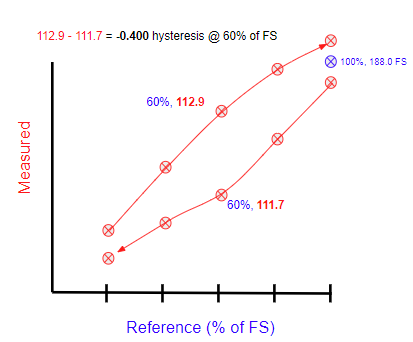
Hysteresis error causes the output to vary depending on the previous input values, the sequence of increasing or decreasing values, or the position in the sensor's full scale range.
Accuracy is the amount of uncertainty in a measurement relative to an absolute standard. Typically defined in terms of gain and offset. Offset errors are given in the unit of the sensor measurement and are independent of the magnitude of the input signal. Gain error depend on the magnitude of the input signal and are expressed as a percentage of the sensor full scale value. Example: Accuracy = +/- (0.1% of input + 1 mV)
Resolution is the smallest change that can be detected in the quantity that is being measured. It can be expressed as either the ratio of the maximum signal measured to the smallest part that can be resolved, or the amount of change that can be detected, expressed as the number of bits (A/D converter bits).
The Characteristic Curve defines the sensor's response to an input in terms of an offset, sensitivity or slope, and linearity.
The calculation of accuracy, repeatability, hysteresis, and linearity should be straight forward, but it is not for two of these items. The International Electrotechnical Commission's (IEC) provides well defined information, but the method for the calculation of accuracy is not specified, and the calculation methods employed for linearity vary considerably from one sensor supplier to another. It is critical that you carefully review how these are calculated before making judgements about the suitability of a sensor for your application.
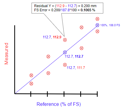
Linearity
The output of the transducer over it’s full span is measured and plotted with a linear regression line. The three most common linearity trend lines applied are terminal point, best fit straight line (BFSL), and zero-based best fit straight line (see IEC 61298-2) . I prefer the BFSL method, which does not require the line to pass through the zero or span points.
The linearity error is the maximum deviation of the sensor output from the BFSL. It may be expressed as an absolute value, or as a percentage of the full scale value.
Hysteresis
Hysteresis is the difference in measured sensor values at points within the same cycle from 0 to full scale and zero again. Those points within a cycle are typically specified as a percentage of the full scale value. The total hysteresis error is the maximum hysteresis error calculated for every point measured across the full span of the sensor.
Repeatability
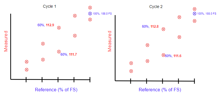
Repeatability is the variation of a measured sensor value at the same point within a cycle, in the same direction, across multiple cycles. The direction referes to if the sensor is exposed to an input from zero to full scale, or from full scale to zero.
Calculation example:
Range @ 60% of FS for 0 to FS from cycle 1 to N = Range(112.9-112.8) = 0.010
Range @ 60% of FS for FS to 0 from cycle 1 to N = Range(111.7-111.6) = 0.010
(repeat calculation of range for 0%, 20%, 40%, 80%, 100%)
Repeatability = max range value for the points evaluated (0%, 20%, 40%, 80%, 100%) = 0.010 mm
% repeatability = 100 * (max range value) / span = 100 * 0.010 / 188.0 = 0.0053%
Accuracy
Accuracy is a composite of the error due to hysteresis, repeatability, and linearity. IEC 61298-2 states that accuracy must include hysteresis, non-repeatability and non-linearity, but it does not state how it should be calculated. The formula below is the calculation I prefer.


.png)